VT-TECHNOLOGY EVOLUTION
Starting point of VT project relates to the capacity of the hydrostatic transmission to deliver electrohydraulic, Continuous Variation Transmission (CVT) performance that can't be matched by electromechanical CVT solutions as it is shown on this video where technology demonstrator proves that hydrostatic transmission allows infinite transmission ratio meaning that output shat can be completely blocked while electric motor runs at nominal speed. More details about demonstrator can be found further below, after introduction...

INTRODUCTION
At present state, of the technological development, mechanical CVT advantage is efficiency, but there is no reason that it can't be matched with efficiency of the hydrostatic CVT solutions. Still as, at present, this is the major advantage of the mechanical over hydrostatical solution this has to be taken into account when system is optimized in order to get performance/cost ratio that can be successful on the market.
Actually, hydrostatic can deliver comparable efficiency to mechanical/electrical system but only in low speed area when flow intensity in the machine is low. This fact was kept in mined at each step of the VT evolution !
This project was started at the end of 2016 and beginning of the 2017, and up today it went through several evolution phases. Through this evolution three main aspects of this new technology came out, covered with up to date three patent applications of which only one came into the public domain WO2020121003A2.
-First aspect: Is related to the capacity of the hydrostatic transmission to provide infinite transmission ratio allowing creation of the completely autoregulated hydrostatic transmission; based on electric standard and available hydrostatic transmission, as presented in video above and below.
This module can be integrated as the rear drive unit onto the vehicle platforms with standard forward drive, i.e. transforming standard front wheel drive unit into the cost efficient Basic Mild Hybrid VT4WD where electrohydraulic approach allowed creation of the autoregulated system that can provide 4WD, ZEV, and boost option up to the 10 km/h using low cost 12 V electric starter without power electronics. Accepting speed limit of around 10 km/h low cost hydrostatic transmission can be used targeting 1000 € option market price. Even it can be realized with existing industrial component NVH is issue so it can be interesting in first instance as accessory in less developed countries where that NVH isn't (yet) as important as in developed countries but it is important to reduce pollution created with slow advancement in traffic jams (les than 10 km/h).
-Second aspect: Is related to the capacity of the hydrostatic transmission to easily change sign of the transmission ratio. Due to that, hydrostatic pump can be integrated onto the assistance belt side side, together with starter/generator. Starter/generators 48 V are already used for light hybridization but low cost versions that are mounted on the assistance belt side so that can't provide ZEV option. Introducing clutch that can separate ICE from the belt, starter/generator 48 V can be used to turn the pump, when ICE is off i.e. provide ZEV option during advancement in traffic jams. On one side this variant will use more expensive hydrostatic machines but as there is no need for additional electric motor target price can be around 1250 €.
-Third aspect: Is related to the most important achievement of the VT approach i.e. hydrostatic modulator. Initially, hydrostatic modulator was seen as the building block needed to align VT - Mild Hybrid technology with other competitive technologies capable to provide
torque vectoring during maneuvering at high speeds i.e. above 50 km/h. Very soon it became apparent that this new device i.e. hydrostatic modulator can be used to create high performance AWD4WD platforms and even active stabilization bars. It is estimated that cost will be centered around 1500 €
Costs estimation is based on experience, and mentioned values seen by the final costumer. Still as cost is strongly related to the size of series, real values can be correctly estimated only with help of the industrial partners like OEM and/or car manufacturer...
Synthesis of the evolution of the VT project can be seen at the image/diagram below
FIRST ASPECT
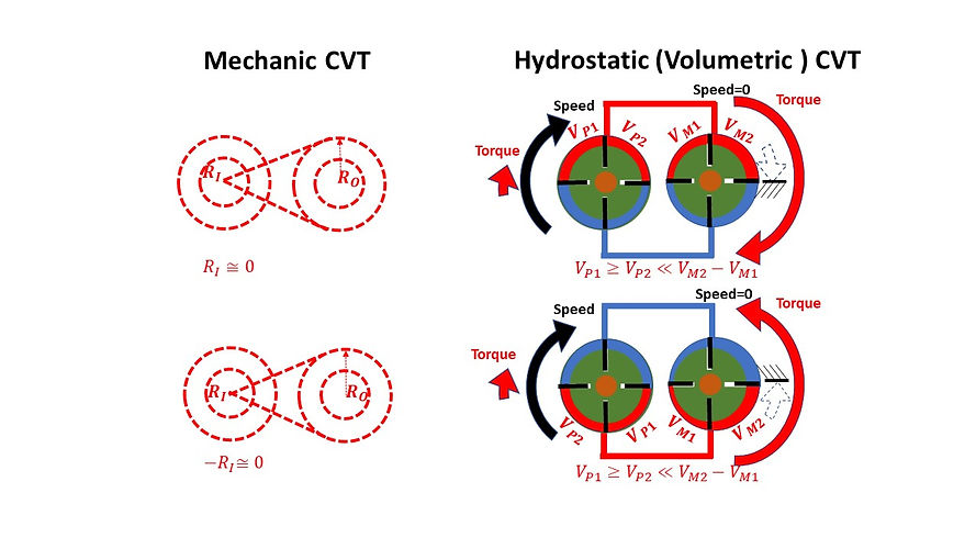
Next figure shows capacity of hydrostatic CVT to perform as mechanical CVT. In this schematic presentation vane pump technology is used as it is, in terms of presentation, more transparent, also it is interesting to mention that pump used in hydraulic steering are vane pump as they are quieter than other technologies. In demonstrator showed on VT4WD basic, technology with balls as the piston is used as more robust and cost effective than other technologies.
Looking onto the figures it can be said that radiuses, at mechanical CVT, are what working volumes (i.e. volumetric machines) are at hydrostatic transmissions. Following proposed logic, what belt is at mechanical CVT that is oil at hydrostatic CVT and this is origin of the advantage of the hydrostatic CVT, as it will be shown on following images.

Following image shows important advantage of the Hydrostatic CVT ant that is ability to hold the load. In terms of the mechanical CVT one should run input wheel with practically almost 0 radius needed to compensate belt slip...there is no belt that can practically work in that condition.
On other hand it is easy to do it with hydrostatic CVT. Pump is set to practically min working displacement needed to compensate volumetric losses due to the leakage and it can hold the output at zero speed and max torque.. As figure shows load can be hold in booth directions and that is additional advantage of the hydrostatic transmission.
Namely in order to do it with belt, CVT pully has to be rotated so that input radius can be considered negative and this isn't practically possible. This will be more transparent on slides regarding change of the rotation direction.
Impossible with mechanic CVT !
Impossible with mechanic CVT !
Based on this, initial qualitative analysis, it is possible to create real demonstrator that will confirm mentioned assumptions.
Simulation work, related to transient phenomenon, was done in Simulink/MATLAB. In order to be more transparent schema is devised into blocks; ELECTRIC MOTOR, HYDRAULIC PUMP, PUMP SELF-ADAPTATION,TYRE DYNAMIC, PACEJKA MODEL, SLOPE, VEHICLE.

ELECTRIC MOTOR consists look-up tables, with supplier data, concerning relation between torque/speed and current/speed. So, with speed from HYDRAULIC PUMP block, values of torque are read and returned to HYDRAULIC PUMP block, Curent data are stored so that courent values can be compared between electromechanical and electrohydraulic unit.
Output from HYDRAULIC PUMP is flow that is input into the HYDRAULIC MOTOR block. Another impute to the HYDRAULIC MOTOR block is speed of the wheel i.e. hydraulic motor so calculating difference between flow delivered by the pump and flow demande by the motor, with integration will give level of the high pressure.
Calculated pressure is input to the PUMP SELF-ADAPTATION block so that actual displacement of the hydraulic pump can be calculated.
Also, inside HYDRAULIC MOTOR block pressure will be transformed to torque that is one of the inputs to the TYRE DYNAMIC block.
In TYRE DYNAMIC block acceleration of the wheel is calculated using difference between torque delivered by the hydraulic motor and torque consumed by the friction between tire and road.
Torque consumed by the contact between tire and road is calculated using friction force calculated as the product of the friction coefficient given by PACEJKA MODEL and normal force level given by the SLOPE block.
This same friction force is input to the VEHICLE block where acceleration and resulting speed of the vehicle will be calculated.
As data for EM used in demonstrator ISKRA AMJ 4726 11.216.050 weren't available on one side and as max 'interesting' power, at this stage of study, for this architecture, with separate electric motor, is estimated as 2.5 kw, simulation work was performed with available data for ISKRA Starter Motor AZE 65 88Ah Current - 80% .
Image below shows comparison between electromechanical system (no power electronics) and electrohydraulic system (no power electronics as well).
Results for electromechanical system are in left column while results for electrohydraulic system are in right column.
For each system four simulations are performed i.e. starting on snow on four different slope / grades 0 [%], 7 [%], 13 [%], 20 [%],

Advantage of the electrohydraulic system is evident as for similar torque on the wheels, only portion of the current is needed during starting. Namely, in electromechanical solutions,, when speed is close to zero efficiency of the electric motor is very pour so that high level of the current are needed to create needed torque, it is well known that in case that electric motor, directly connected to the battery, will ve destroyed by heat if it is kept at zero speed. Also, as it can be seen from the figures, and as it is also well known, with increased speed efficiency of the electric motor will be increased and current level will dorp as wel as heating of the motor itself.
On contrary, with electrohydraulic autoregulated system, electric motor can run close to nominal speed even output shaft is et zero speed so even for motor that is integrated into the system exposed to need of high torque and low speed electric motor, as it will run close to nominal speed will be less stressed in electrohydraulic system than in electromechanical system.
Well it has to be mentioned that electrohydraulic systems have disadvantage of the lower overall efficiency. Namely they have good efficiency in low speed high torque conditions, while in low torque, especially high speed range they are loosing they advantage over electromechanical systems. Therefore this has to be kept in mined as electrohydraulic will bring the benefit only it is well adapted for the given application, namely in synergy with rest of the system as it is shown in SAE paper 'Introducing Hydraulic-Electric Synergy into Hybrid Transmission Using the Free-piston Engine Technology' https://www.sae.org/publications/technical-papers/content/2007-01-4112/.
Efficiency of the hydrostatic transmissions strongly depends of the technology that is used. In presented demonstrator simplest hydrostatic machines are used , so that peek efficiency for combination pump x motor is of 0.77 x 0.77 = 0.6 . More expensive technologies, in combination pump x motor can reach 0.92 x 0.92 = 0.85. It has to be mentioned that this performance can be improved even more so better results, as recently is shown by introduction of the new technology ; https://www.innas.com/floating-cup.html
In technology demonstrator, already presented and shown again in video below, capacity to hold the load is clearly presented. One can see hand brake and reducer needed to integrate brake. Load, that ahs to be hold is simulated using brake to block output shaft. In automotive applications this corresponds to the car starting on the step slope, while brake release corresponds to acceleration of the car on flat surface.
Autoregulated Hydrostatic Transmissions acts as Continuous Variable Transmission with capacity of infinite conversion range , as video of demonstrator clearly proves. When output shaft is blocked conversion rate is automatically set to infinite i.e. electric motor is kept close to nominal rpm/power while output torque is limited only by the resistance of the mechanical parts and/or efficiency. Therefore electrohydraulic solutions are perfect match for the applications where high torque and low speeds has to be handled. In this case intention is to use it in vehicles but this fixture is useful in winches and other applications where high, variable, torque, has to be handled at low speed.
Using autoregulated hydrostatic transmission, presented in the video, it is possible to provide electric rear axle where, using 1500 W 12V DC electric motor, according to simulations, will be possible to provide assistance 0-10 km/h with max (intermittent) torque 400 Nm.
Using stronger model of the autoregulated hydrostatic transmission it will be possible to cover range of 0-33 km/h with max. intermittent torque of 400 Nm.
Namely max speed is set by construction of the autoregulated transmission i.e. speed and torque limit of the transmission itself. and needed output torque. Needed output torque, at wheel, will set transmission ratio needed to get needed torque on the wheel and from it and speed limit of the transmission itself will set wheel speed as well.
400 Nm is taken as max torque that can be consumed on slope of 20% , in snow conditions, more torque will simply generate wheel slip. If higher torque is needed that will reduce max speed proportionally to max torque increase.
It has to be mentioned that this calculation is performed with value that constructer of the transmission indicates as intermittent power. If peak value is taken as max higher speed range will be possible (to be investigated).
Constant power diagrams are given below. Autoregulated transmission is capable to adjust transmission ratio so that for each speed torque is adjusted so that power consumption is constant) . Horizontal lines presents rolling resistance and effect of the slope inclination that has to be overtaken by power of the electric motor.
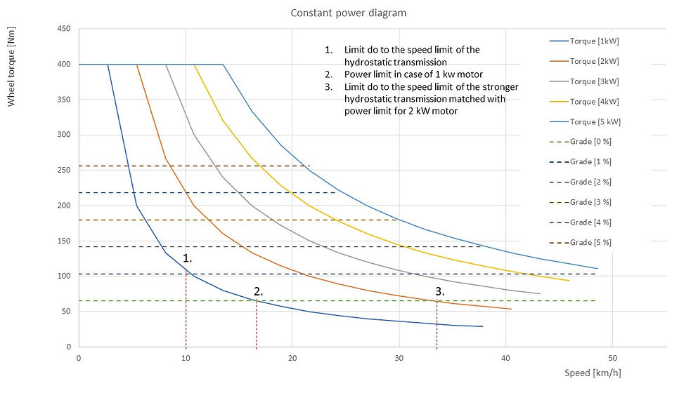
Covering range of only 0-10/(33) km/h is sufficient to provide:
-to get out from situation where front wheels are slipping,
-creep fonction in trafic jams
-simplified starting and parking maneuvering on slopes
-adding batteries it is possible to advance in trafic jams without turning on car engine (ZEV mode).
As 1500 w is power of todays alternators no modification of the engine compartment isn't needed so industrialization is very straight forward.
As it is shown, by video, autoregulation can keep electromotor rpm close to nominal range, nevertheless the speed at the output; therefore it can be assumed that level of Technological Redines Level TRL-3 is achieved..
As for any project, related to hydrostatic transmission aimed to reach automotive market NVH performance has to be honed and this, as well as fine tuning of the control performance, is subject of the ongoing development of the demonstrator needed to pass TRL 5.
As NVH performance is closely linked to integration into targeted vehicle platform, OEM partner(s) are welcomed to participate in further development of this project.
SE
SECOND ASPECT
Aanother advantage of the hydrostatic CVT is that output rotation direction can be easily changed by the variation of the flow direction. Variation of the ratio, between working volume of the pump and motor different ratios of the transformation can be obtained..

Impossible with mechanic CVT !
Impossible with mechanic CVT !
Using this advantage one pump connected to ICE, running in same direction can provide positive and negative flow allowing forward and revers motion. Introducing clutch ICE can be disconnected and 48 V starter/generator can be used to provide ZEV mode.

Aim of this work is to show that electrohydraulic systems can offer more cost effective solutions due to the explained capacity of the CVT with infinite transmission ratio and capacity to easily change sign of transmission. If automotive industry shows larger support in R&D as it is case for other systems progress can be made so that efficiency can be further improved and evidence of the advantage of the electrohydraulic systems will be even more evident
In the table below one can find estimated relation between electrohydraulic 12/48 V and electric 48V technology, at the present stat of the development. This is only estimation and due to the ongoing R&D it is expected that it will further change in the future.
